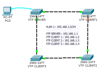
Diagramma di rete
Lo scopo di questo laboratorio è testare la tua capacità di configurare VLAN e VTP su una piccola rete di 4 switch utilizzando Packet Tracer 7.2.1.
Questo laboratorio ti aiuterà a preparare il testlet VTP e le domande simlet dell’esame Cisco ICND1 .

Istruzioni di laboratorio
1.Configurare lo switch VTP-SERVER come server VTP
2.Collegare agli altri 3 switch e configurarli come client VTP.
Tutti i collegamenti tra gli swich devono essere configurati come linee di collegamento.
3.Configurare il nome del dominio VTP come “TESTDOMAIN” e la password VTP come “cisco”
4.Configurare VLAN 10 con il nome “STUDENTS” e VLAN 50 con il nome “SERVERS”
5. Controllare la propagazione su tutti gli switch del dominio VTP.
Soluzione di laboratorio VLAN e VTP
1. Configurare lo switch VTP-SERVER come server VTP
VTP-SERVER(config)#vtp mode serverVerificare la modalità operativa VTP utilizzando il comando show vtp status
VTP-SERVER#show vtp status
VTP Version                     : 2
Configuration Revision          : 4
Maximum VLANs supported locally : 255
Number of existing VLANs        : 7
VTP Operating Mode              : Server
VTP Domain Name                 : TESTDOMAIN
VTP Pruning Mode                : Disabled
VTP V2 Mode                     : Disabled
VTP Traps Generation            : Disabled
MD5 digest                      : 0xAE 0x4F 0x3F 0xC5 0xD3 0x41 0x9C 0x11
Configuration last modified by 192.168.1.1 at 3-1-93 00:27:41
Local updater ID is 192.168.1.1 on interface Vl1 (lowest numbered VLAN interface found)
2. Connettersi agli altri 3 switch Catalyst e configurarli come client VTP.
Tutti i collegamenti tra gli swich devono essere configurati come linee di collegamento.
VTP-CLIENT3(config)#vtp mode clientClient in modalità #vtp VTP-CLIENT3 (config)
Verificare la modalità operativa VTP dello switch utilizzando il comando show vtp status . Lo shoud “Modalità operativa VTP” ha il valore “Client”. Di seguito viene fornito un esempio con lo switch VTP-CLIENT3.
VTP-CLIENT3#sh vtp status
VTP Version                     : 2
Configuration Revision          : 4
Maximum VLANs supported locally : 255
Number of existing VLANs        : 7
VTP Operating Mode              : Client
VTP Domain Name                 : TESTDOMAIN
VTP Pruning Mode                : Disabled
VTP V2 Mode                     : Disabled
VTP Traps Generation            : Disabled
MD5 digest                      : 0xAE 0x4F 0x3F 0xC5 0xD3 0x41 0x9C 0x11
Configuration last modified by 192.168.1.1 at 3-1-93 00:27:41
Configurare ogni collegamento tra switch come linea di collegamento usando il comando truink in modalità switchport
interface GigabitEthernet1/1
switchport mode trunk

interface GigabitEthernet1/2
switchport mode trunk
3. Configurare il nome del dominio VTP come “TESTDOMAIN” e la password VTP come “cisco”
Sull’interruttore Catalyst del server VTP:
VTP-SERVER(config)#vtp domain TESTDOMAIN
VTP-SERVER(config)#vtp password cisco
Su ogni switch client VTP:
VTP-CLIENT1(config)#vtp password cisco
VTP-CLIENT1(config)#vtp domain TESTDOMAIN
4. Configurare VLAN 10 con il nome “STUDENTI” e VLAN 50 con il nome “SERVER”
Sul commutatore Catalyst 2960 del server VTP, configura i seguenti comandi per creare vlans “STUDENTI” e “SERVI”:
VTP-SERVER(config)#vlan 10
VTP-SERVER(config-vlan)#name STUDENTS
VTP-SERVER(config)#vlan 50
VTP-SERVER(config-vlan)#name SERVERS
5. Verificare la propagazione dei vlan “STUDENTS” e “SERVERS” su tutti gli switch di rete Catalyst 2960 del dominio VTP.
Utilizzare il brief show vlan su ciascun interruttore per verificare la propagazione dei 2 VLAN.
VTP-SERVER#show vlan brief

VLAN Name                             Status    Ports
---- -------------------------------- --------- -------------------------------
1    default                          active    Fa0/1, Fa0/2, Fa0/3, Fa0/4, [...]
10   STUDENTS                         active
50   SERVERS                          active
1002 fddi-default                     active
1003 token-ring-default               active
1004 fddinet-default                  active
1005 trnet-default                    active